Servo Motor Control
This will be done using an Android emulator. March of empires for pc. Writing your epic story and become a Legend!Are you a fan of Tower Defense game? You have played many TD game like Kingdom Rush, Download Kingdom Defense 2: Empire Warriors today, great game for you.Follow us to get more infomation:Fanpage: How to download and run Kingdom Defense 2: Empire Warriors – Premium on your PC and MacKingdom Defense 2: Empire Warriors – Premium For PC can be easily installed and used on a desktop computer or laptop running Windows XP, Windows 7, Windows 8, Windows 8.1, Windows 10 and a Macbook, iMac running Mac OS X. To install Kingdom Defense 2: Empire Warriors – Premium For PC, we will use BlueStacks app player.
Servo motors are great devices that can turn to a specified position.Usually, they have a servo arm that can turn 180 degrees. Using the Arduino, we can tell a servo to go to a specified position and it will go there. As simple as that!Servo motors were first used in the Remote Control (RC) world, usually to control the steering of RC cars or the flaps on a RC plane. With time, they found their uses in robotics, automation, and of course, the Arduino world.Here we will see how to connect a servo motor and then how to turn it to different positions.The first motor I ever connected to an Arduino, seven years ago, was a Servo motor. Nostalgic moment over, back to work!We will need the following things:.
Continuous rotation servo motors are actually a modified version of what the servos are actually meant to do, that is, control the shaft position. The 360 o rotation servos are actually made by changing certain mechanical connections inside the servo. However, a certain manufacturer like parallax sells these servos as well. A servo motor is a motor whose shaft turns to position something based off a control signal. They are typically used to steer remote control airplanes by adjusting the wing flaps, flight position for drones, controlling valves used in flow control or continuous drive of wheels for robots.
An Arduino board connected to a computer via USB. A servo motor. Jumper wiresThere are few big names in the servo motor world. Hitec and Futaba are the leading RC servo manufacturers.
Good places to buy them are,. This instructable and many more can be found in my Arduino Development Cookbook available.:D. A servo motor has everything built in: a motor, a feedback circuit, and most important, a motor driver.
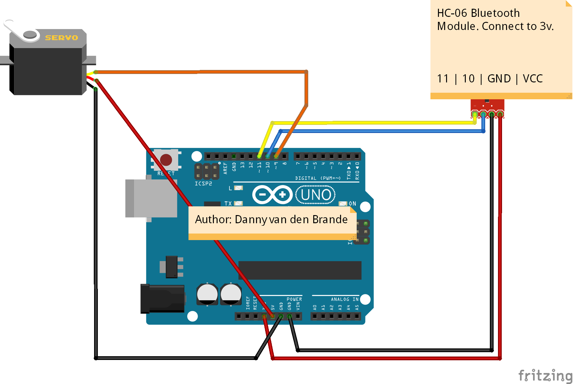
It just needs one power line, one ground, and one control pin.Following are the steps to connect a servo motor to the Arduino:. The servo motor has a female connector with three pins. The darkest or even black one is usually the ground. Connect this to the Arduino GND. Connect the power cable that in all standards should be red to 5V on the Arduino.
Connect the remaining line on the servo connector to a digital pin on the Arduino.Check the image for a view of the servo connected to the Arduino. Servos are clever devices.
Using just one input pin, they receive the position from the Arduino and they go there. Internally, they have a motor driver and a feedback circuit that makes sure that the servo arm reaches the desired position. But what kind of signal do they receive on the input pin?It is a square wave similar to PWM. Each cycle in the signal lasts for 20 milliseconds and for most of the time, the value is LOW. At the beginning of each cycle, the signal is HIGH for a time between 1 and 2 milliseconds. At 1 millisecond it represents 0 degrees and at 2 milliseconds it represents 180 degrees. In between, it represents the value from 0–180.
This is a very good and reliable method. The graphic makes it a little easier to understand.Remember that using the Servo library automatically disables PWM functionality on PWM pins 9 and 10 on the Arduino UNO and similar boards. Dead cells guide.
Code breakdownThe code simply declares the servo object and then initializes the servo by using the servo.attach function. We shouldn't forget to include the servo library. In the loop, we set the servo to 0 degrees, wait, then set it to 90, and later to 180 degrees.
Controlling servos is easy, and here are a few more tricks we can use: Controlling the exact pulse timeArduino has a built-in function servo.write(degrees) that simplifies the control of servos. However, not all servos respect the same timings for all positions. Usually, 1 millisecond means 0 degrees, 1.5 milliseconds mean 90 degrees, and, of course, 2 milliseconds mean 180 degrees. Some servos have smaller or larger ranges.For better control, we can use the servo.writeMicroseconds(us) function, which takes the exact number of microseconds as a parameter.
Remember, 1 millisecond equals 1,000 microseconds. More servosIn order to use more than one servo, we need to declare multiple servo objects, attach different pins to each one, and address each servo individually. First, we need to declare the servo objects—as many as we need: // Create servo objectsServo Servo1, Servo2, Servo3;Then we need to attach each object to one servo motor. Remember, every servo motor uses an individual pin: Servo1.attach(servoPin1);Servo2.attach(servoPin2);Servo3.attach(servoPin3);In the end, we just have to address each servo object individually: Servo1.write(0); // Set Servo 1 to 0 degreesServo2.write(90); // Set Servo 2 to 90 degreesConnection-wise, the grounds from the servos go to GND on the Arduino, the servo power to 5V or VIN (depending on the power input), and in the end, each signal line has to be connected to a different digital pin. Contrary to popular belief, servos don't need to be controlled by PWM pins—any digital pin will work. Continuous rotation servosThere is a special breed of servos labelled as continuous rotation servos. While a normal servo goes to a specific position depending on the input signal, a continuous rotation servo either rotates clockwise or counter-clockwise at a speed proportional to the signal.
For example, the Servo1.write(0) function will make the servomotor spin counter-clockwise at full speed. The Servo1.write(90) function will stop the motor and Servo1.write(180) will turn the motor clockwise at full speed.There are multiple uses for such servos; however, they are really slow. If you are building a microwave and need a motor to turn the food, this is your choice.
But be careful, microwaves are dangerous! In his library he writes a degree to the servo and it moves there. Set up a loop that increases the degree by say. 1 every time it loops and put a delay in the loop. When you get to the position you want get out of the loop.
That will get you to move in degrees per second (you can also use the millis instruction so you can do other things and not actually stop the microcontroller. The millis instruction is more complex but basically you are taking a free running clock time with millis and comparing it to the last time you got the millis instruction. This allows the controller to continue executing main and does not just stop and sit on a delay not operating the rest of the code. Are you confused yet?). One note, the on-board regulator is only good for up to 3 large servos, before you are drawing too much, that the Arduino mpu itself, begins to brown-out/reset. Then, you'll want to supply the servos externally, say with a 7805 regulator, which can still be fed from the main supply (parallel to the voltage going to the barrel socket.
Highly advise against drawing through the VIn pin on the arduino, as this is still a thin trace that could burn/break)One odd thing, despite the in-IDE example saying you can only assign 8 servo devices, ALL digital pins, 0 through 13, can be used (without serial I/O), but kinda pushing the limits. The mega only has 15 PWM pins.
You would probably need multiple boards with one master and two slaves communicating. As for power All you do is get a 5v power supply. Connect the ground of the power supply to the board and servos (everything must have a common ground to communicate unless you use opticouplers/relays) and use the power of the supply to the servos (it can power the arduino board too). Make sure to wire them directly to the supply.
You dont want to pull all of the current through the small trace on the arduino board. Also if your arduino starts having issues when trying to run multiple servos you MAY need filtering caps to keep the noise out of the microcontroller.
Servo control is achieved by sending a servo a PWM signal, a series of repeating pulses of variable width where either the width of the pulse (most common modern hobby servos) or the duty cycle of a pulse train (less common today) determines the position to be achieved by the servo. The PWM signal might come from a receiver to the or from common such as the.Small hobby servos (often called radio control, or RC servos) are connected through a standard three-wire connection: two wires for a DC power supply and one for control, carrying the control pulses.The parameters for the pulses are the minimal pulse width, the maximal pulse width, and the repetition rate. Given the rotation constraints of the servo, neutral is defined to be the center of rotation. Different servos will have different constraints on their rotation, but the neutral position is always around 1.5 milliseconds (ms) pulse width. In modern RC servos the angle of mechanical rotation is determined by the width of an electrical pulse that is applied to the control wire.
This is a form of. The typical RC servo expects to see a pulse every 20 ms, however this can vary within a wide range that differs from servo to servo. The width of the pulse will determine how far the motor turns. For example, in many RC servos a 1.5 ms pulse will make the motor turn to the 90° position (neutral position).
The low time (and the total period) can vary over a wide range, and vary from one pulse to the next, without any effect on the position of the servo motor.Modern RC servo position is not defined by the PWM duty cycle (i.e., ON vs OFF time) but only by the width of the pulse. (This is different from the PWM used, for example, in some DC motor speed control). Most RC servos move to the same position when they receive a 1.5 ms pulse every 6 ms (a duty cycle of 25%) as when they receive a 1.5 ms pulse every 25 ms (a duty cycle of 6%) – in both cases, they turn to the central position (neutral position). With many RC servos, as long as the refresh rate (how many times per second the pulse is sent, aka the pulse repetition rate) is in a range of 40 Hz to 200 Hz, the exact value of the refresh rate is irrelevant.The period of 20 ms (50 Hz) comes from the days where the signal was encoded in PPM format to be sent over the air. The PPM period was around 22.5 ms, and the conversion to PWM was trivial: the time of the PWM high state was the time position of the PPM pulse for that servo.Most RC receivers send pulses to the RC servo at some constant frame rate, changing only the high time. However, it is possible to command an RC servo to move over its entire range with a function generator set to a constant 10% duty cycle by changing only the frequency (frame rate).
Force When these servos are commanded to move, they will move to the position and hold that position. If an external force pushes against the servo while the servo is holding a position, the servo will resist from moving out of that position.
The maximal amount of force the servo can exert is the torque rating of the servo. Servos will only hold their position for their timeout duration, though; the position pulse must be repeated, usually within 20ms, to instruct the servo to stay in position.Variations When a pulse is sent to a servo that is less than 1.5 ms, the servo rotates to a position and holds its output shaft some number of degrees counterclockwise from the neutral point. When the pulse is wider than 1.5 ms the opposite occurs.
The minimal and maximal widths of pulse that will command the servo to turn to a valid position are functions of each servo. Different brands, and even different servos of the same brand, will have different maxima and minima. Generally, the minimal pulse will be about 1 ms wide, and the maximal pulse will be 2 ms wide.See also.References.